FAA obstruction lighting types
There are eight types of obstruction lights covering low intensity, medium intensity and high intensity in FAA framework.
| Types | Description |
|---|---|
| L-810 | Steady-burning red obstruction light |
| L-810 (F) | Flashing red obstruction light, 30 Flashes Per Minute (FPM) |
| L-856 | High intensity flashing white obstruction light, 40 Flashes Per Minute (FPM) |
| L-857 | High intensity flashing white obstruction light, 60 FPM |
| L-864 | Flashing red obstruction light, 30 FPM |
| L-865 | Medium intensity flashing white obstruction light, 40 FPM |
| L-866 | Medium intensity flashing white obstruction light, 60 FPM |
| L-885 | Flashing red obstruction light, 60 FPM |
Lighting Equipment’ by FAA Airport Engineering Division (AAS-100) 2019, Specification for Obstruction
Lighting Equipment, AC 150/5345-43J, p. 7. Copyright 2019 by FAA Airport Engineering Division (AAS-100), 202-267-7669.
L-810
| Light Type | Color | Signal type (flash rate) | Vertical Beam Spread | Horizontal Beam Spread | Effective Intensity | The Center of the vertical beam spread |
|---|---|---|---|---|---|---|
| L-810 | Red | Steady burning | ≥10° | 360° | ≥32.5cd | +4° — +20° |
| L-810 (F) | Red | Flashing (30FPM±3FPM) | ≥10° | 360° | ≥32.5cd | +4° — +20° |
Where L-810 (F) and L-864 units are deployed on a same structure, L-810 (F) units shall flash synchronously with L-864 at 30FPM ± 3FPM.
L-864, L-885
| Light Type | Color | Signal type (flash rate) | Vertical Beam Spread | Horizontal Beam Spread | Effective Intensity | Intensity at 0° Vertical elevation angle |
|---|---|---|---|---|---|---|
| L-864 | Red | Flashing (30FPM) | ≥3° (≥750cd) | 360° | 2,000cd±25% | ≥1,500cd |
| L-885 | Red | Flashing (60FPM) | ≥3° (≥750cd) | 360° | 2,000cd±25% | ≥1,500cd |
In practical installation of L-864/L-885, obstruction objects may near obstruction lighting units. Therefore, FAA (2019) in AC 150/5345-43J stresses that “Multiple light units may be used to achieve a horizontal coverage of 360 degrees”.
L-865, L-866
| Light Type | Color | Step | Vertical Beam | Horizontal spread | Effective Intensity | Intensity at 0° Vertical elevation angle | Intensity at -10° Vertical elevation angle |
|---|---|---|---|---|---|---|---|
| L-865 (40FPM), L-866 (60FPM) | White | Day/Twilight | ≥3° (≥7500cd) | 360° | 20,000cd±25% | ≥15,000cd | ≤750cd |
| L-865 (40FPM), L-866 (60FPM) | White | Night | ≥3° (≥750cd) | 360° | 2,000cd±25% | ≥1,500cd | ≤75cd |
In practical installation of L-865/L-866, obstruction objects may near obstruction lighting units. Therefore, FAA (2019) in AC 150/5345-43J stresses that “Multiple light units may be used to achieve a horizontal coverage of 360 degrees”.
L-856
| Light Type | Color | Step | Vertical Beam | Horizontal spread | Effective Intensity | Intensity at 0° Vertical elevation angle | Intensity at -10° Vertical elevation angle |
|---|---|---|---|---|---|---|---|
| L-856 (40FPM) | White | Day | 3°-7° (≥75000cd) | 90° / 120° | 200,000cd±25% | ≥150,000cd | ≤7500cd |
| L-856 (40FPM) | White | Twilight | 3°-7° (≥7500cd) | 90° / 120° | 20,000cd±25% | ≥15,000cd | ≤750cd |
| L-856 (40FPM) | White | Night | 3°-7° (≥750cd) | 90° / 120° | 2,000cd±25% | ≥1,500cd | ≤75cd |
In practical installation of L-856, obstruction objects may near obstruction lighting units. Therefore, FAA (2019) in AC 150/5345-43J stresses that “Multiple light units may be used to achieve a horizontal coverage of 360 degrees”.
L-857
| Light Type | Color | Step | Vertical Beam | Horizontal spread | Effective Intensity | Intensity at 0° Vertical elevation angle | Intensity at -10° Vertical elevation angle |
|---|---|---|---|---|---|---|---|
| L-857 (60FPM) | White | Day | 3°-7° (≥52500cd) | 90° / 120° | 140,000cd±25% | ≥105,000cd | ≤4725cd |
| L-857 (60FPM) | White | Twilight | 3°-7° (≥7500cd) | 90° / 120° | 20,000cd±25% | ≥15,000cd | ≤750cd |
| L-857 (60FPM) | White | Night | 3°-7° (≥750cd) | 90° / 120° | 2,000cd±25% | ≥1,500cd | ≤75cd |
In practical installation of L-857, obstruction objects may near obstruction lighting units. Therefore, FAA (2019) in AC 150/5345-43J stresses that “Multiple light units may be used to achieve a horizontal coverage of 360 degrees”.
Red Obstruction Lighting for Poles, Towers, and Similar Skeletal Structures
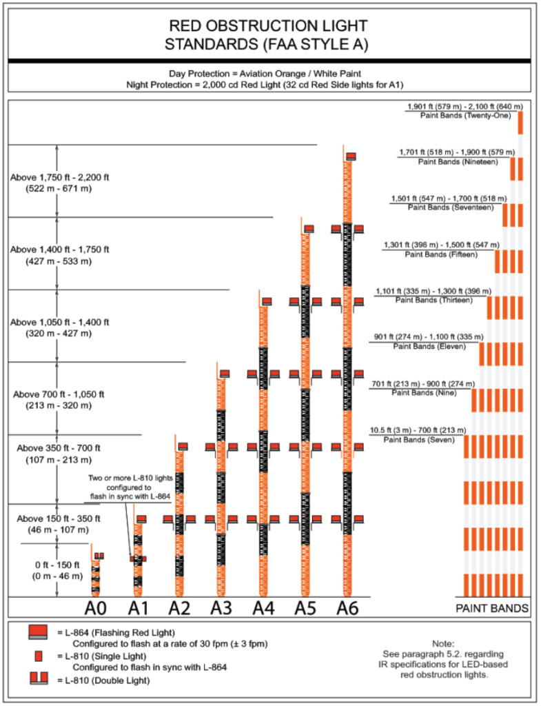
FAA Airspace Service (2015 pp. 25-26) depicted the application of red obstruction lights (L-810 & L-864) for painted skeletal structures, such as telecommunication towers, radio towers, television towers, supporting structures for overhead transmission lines, and similar structures, in chapter 5 Red Obstruction Light System of AC 70/7460-1L.
- Top-Mounted Obstruction Light.
a. Structures 150 Feet (46 m) AGL or Less. Two or more steady-burning red (L810) lights should be installed in a manner to ensure an unobstructed view of one or more lights by a pilot.
b. Structures Exceeding 150 Feet (46 m) AGL. At least one red flashing (L-864) light should be installed in a manner to ensure an unobstructed view of one or more lights by a pilot.
c. Appurtenances 40 Feet (12 m) or Less. If a rod, antenna, or other appurtenance 40 feet (12 m) or less in height is incapable of supporting a red flashing light, then it may be placed at the base of the appurtenance. If the mounting location does not allow an unobstructed view of the light by a pilot, then additional lights should be added.
d. Appurtenances Exceeding 40 Feet (12 m). If a rod, antenna, or other appurtenance exceeding 40 feet (12 m) in height is incapable of supporting a red flashing light, a supporting mast with one or more lights should be installed adjacent to the appurtenance. Adjacent installations should not exceed the appurtenance’s height and be within 40 feet (12 m) of the tip to allow the pilot an unobstructed view of at least one light. If the rod, antenna, or other appurtenance is 7/8 inch wide or more, at least two lights must be installed on the supporting mast to provide the necessary unobstructed view. - Mounting Intermediate Levels. The number of light levels is determined by the height of the structure, including all appurtenances, as shown in
Figure A-7in Appendix A. The number of lights on each level is determined by the shape and height of the structure. These lights should be mounted to ensure an unobstructed view of at least one light by a pilot.
a. Steady-Burning Lights (L-810).
i. Structures 150 Feet (46 m) AGL or Less. Two or more steady-burning (L-810) lights should be installed diagonally or on diametrically opposite positions.
ii. Structures Exceeding 150 Feet (46 m) AGL. These structures do not require steady-burning (L-810) lights.
b. Flashing Lights (L-810). For structures exceeding 151 feet (46 m) but not more than 350 feet (107 m) at intermediate levels, two or more flashing (L-810) lights should be mounted outside at diagonally opposite positions of intermediate levels. These lights should be configured to flash simultaneously with the L864 flashing light on the top of the structure at a rate of 30 flashes per minute (fpm) (± 3 fpm).
c. Flashing Lights (L-864).
i. Structures 350 Feet (107 m) AGL or Less. These structures do not require flashing (L-864) lights at intermediate levels.
ii. Structures Exceeding 350 Feet (107 m) AGL. At intermediate levels, as shown inFigure A-7in Appendix A, two (L-864) lights should be mounted outside at diagonally opposite positions.
Red Obstruction Lighting for Chimneys, Flare Stacks, and Similar Solid Structures
Number of Light Units.
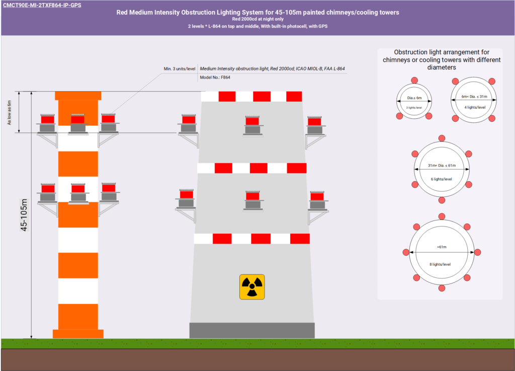
The number of units recommended depends on the diameter of the structure at the top. The number of lights recommended below is the minimum.
1. Structures 20 Feet (6 m) or Less in Diameter. Three light units per level.
2. Structures Exceeding 20 Feet (6 m) but not More Than 100 Feet (31 m) in Diameter. Four light units per level.
3. Structures Exceeding 100 Feet (31 m) but not More Than 200 Feet (61 m) in Diameter. Six light units per level.
4. Structures Exceeding 200 Feet (61 m) in Diameter. Eight light units per level.
Top-Mounted Obstruction Lights.
1. Structures 150 Feet (46 m) AGL or Less. L-810 lights should be installed horizontally at regular intervals at or near the top.
2. Structures Exceeding 150 Feet (46 m) AGL. At least three L-864 lights should be installed.
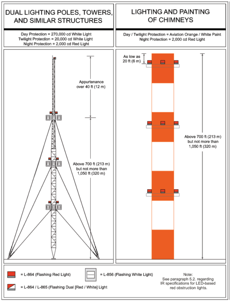
3. Chimneys, Cooling Towers, and Flare Stacks. Lights may be displayed as low as 20 feet (6-m) below the top (see Figure A-14 in Appendix A) to avoid the obscuring effect of deposits and heat generally emitted by this type of structure. It is important that these lights are readily accessible for cleaning and lamp replacement. It is understood that with flare stacks, as well as any other structures associated with the petrol-chemical industry, normal lighting requirements may not be necessary. This could be due to the location of the flare stack/structure within a large, well-lighted, petrol-chemical plant, or the fact that the flare, or working lights surrounding the flare stack/structure, is as conspicuous as obstruction lights.
Mounting Intermediate Levels.
The number of light levels is determined by the height of the structure including all appurtenances. For cooling towers 600 feet (183 m) AGL or less, intermediate light levels are not necessary. Structures between 150 feet and 350 feet AGL or less should have a second level of steady-burning red light units installed approximately at the midpoint of the structure and in a vertical line with the top level of lights. Structures exceeding 350 feet (107 m) AGL should have a second level of flashing light units.
1. Steady-Burning (L-810) Lights. The recommended number of light levels is shown in Figure A-18 in Appendix A. At least three lights should be installed on each level.
2. Flashing (L-864) Lights. The recommended number of light levels is shown in Figure A-7 in Appendix A. At least three lights should be installed on each level.
a. Structures 350 Feet (107 m) AGL or Less. These structures do not need intermediate levels of flashing lights.
b. Structures Exceeding 350 Feet (107 m) AGL. At least three flashing (L-864) lights should be installed on each level in a manner, allowing an unobstructed view of at least one light.
Red Obstruction Lighting for Prominent Buildings and Similar Extensive Obstructions
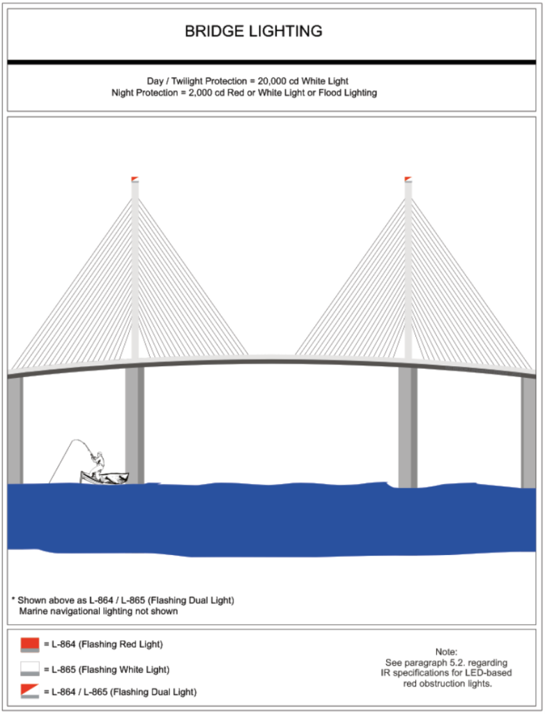
When objects within a group of obstructions are approximately the same overall height above the surface and are located a maximum of 150 feet (46 m) apart, the group of obstructions may be considered an extensive obstruction. Light units should be installed on the same horizontal plane at the highest portion, or edge, of the prominent obstructions. Light units should be placed to ensure the light is visible to a pilot approaching from any direction. If the structure is a bridge and is over navigable water, the sponsor must obtain prior approval of the lighting installation from the Commander of the District Office of the U.S. Coast Guard to avoid interference with marine navigation. Steady-burning lights should be displayed to indicate the extent of the obstruction, as follows:
1. Structures 150 Feet (46 m) or Less in Any Horizontal Direction. If the structure/bridge/extensive obstruction is 150 feet (46 m) or less horizontally, at least one steady-burning light (L-810) should be displayed on the highest point at each end of the obstruction’s major axis. If this is impractical because of the overall shape, display a double obstruction light in the center of the highest point.
2. Structures Exceeding 150 Feet (46 m) in at Least One Horizontal Direction. If the structure/bridge/extensive obstruction exceeds 150 feet (46 m) horizontally, at least one steady-burning light should be displayed for each 150 feet (46 m), or fraction thereof, of the overall length of the major axis. At least one of these lights should be displayed on the highest point at each end of the obstruction. Additional lights should be displayed at approximately equal intervals, not to exceed 150 feet (46 m) on the highest points along the edge between the end lights. If an obstruction is located near a landing area and two or more edges are the same height, the edge nearest the landing area should be lighted.
3. Structures Exceeding 150 Feet (46 m) AGL. Steady-burning red obstruction lights should be installed on the highest point at each end. At intermediate levels, steady-burning red lights should be displayed for each 150 feet (46 m), or fraction thereof. The vertical position of these lights should be equidistant between the top lights and the ground level, as the shape and type of obstruction will permit. A steady-burning red light should be displayed at each outside corner on each level with the remaining lights evenly spaced between the corner lights.
4. Exceptions. Flashing red lights (L-864) may be used instead of steady-burning lights if early or special warning is necessary. These lights should be displayed on the highest points of an extensive obstruction at intervals not exceeding 3,000 feet (915 m). At least three lights should be displayed on one side of the extensive obstruction to indicate a line of lights. (See Figure A-25 in Appendix A.)
Medium Intensity White Flashing Obstruction Lighting for Radio and Television Towers and Similar Skeletal Structures
Reference
FAA Airport Engineering Division (AAS-100), 202-267-7669 2019, AC 150/5345-43J, Specification for Obstruction Lighting Equipment, 3/11/2019 (errata updates 4/29/2019), AAS-100, Office of Airport Safety & Standards – Airport Engineering Division, Washington, DC 20591, viewed 24 October 2020, < https://www.faa.gov/documentLibrary/media/Advisory_Circular/150-5345-43J.pdf>.
FAA Airspace Service (AJV-15) 2018, AC 70/7460-1L, Obstruction Marking and Lighting, FAA Airspace Service (AJV-15), Washington, DC 20591, viewed 24 October 2020, < https://www.faa.gov/documentLibrary/media/Advisory_Circular/AC_70_7460-1L_-_Obstuction_Marking_and_Lighting_-_Change_2.pdf>.

