Lighting of obstacles
4.101 Obstacle lights should be used to indicate the existence of objects which are to be lit as follows:
- Low intensity steady red obstacle lights should be used on obstacles less than 45 m high, except that medium intensity steady red lights should be used to light such obstacles as an elongated structure, an obstacle in the outer area of the approach or high ground adjacent to the aerodrome circuit. There are two types of low intensity obstacle lights for fixed obstacles:
Group A and Group B (see table 6A.1).
a) Low intensity Group A lights should be used for obstacles on the movement area where Group B lights may cause dazzle.
b) Low intensity Group B lights should be used away from the movement area or in areas on the movement area with high levels of background illuminance. - Medium intensity red steady obstacle lights should be used on obstacles between 45 m and less than 150 m in height.
- Medium intensity steady red obstacle lights should be used to indicate the presence of:
a) an obstacle if its height is 150 m or more; or
b) a tower supporting overhead wires, cables etc. of any height where an aeronautical study indicates such lights to be essential for recognition of the presence of the obstacle.
4.102 However, where an aeronautical study conducted by the CAA concludes that greater conspicuity of the obstacle through the use of a higher specification
light is required, the use of a high intensity flashing white obstacle light will be considered by the CAA.
4.103 The combination of white and red obstacle lights should not be used at the same time to light an obstacle.
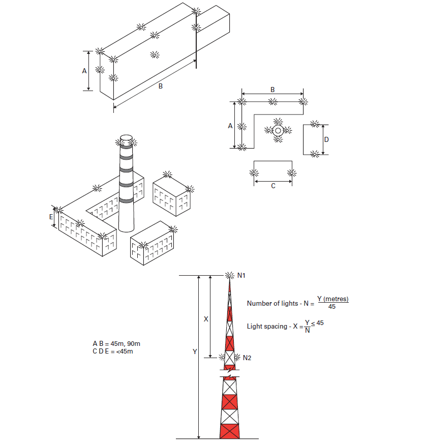
Location of obstacle lights (figure 4.18)
4.104 The top light
- Except in the case of a chimney or other similar structure, one or more lights should be located at the top of the obstacle. The lights should be so arranged as to indicate the highest points or edges of the obstacle relative to the obstacle limitation surface. If two or more edges are of the same height, the edge nearest the flight path should be lit. On facing sides of groups of obstacles, lights may be omitted with the approval of the CAA, and the group treated as one solid obstacle.
- In the case of a chimney or other similar structure, the top light should be placed between 1.5 m and 3.0 m below the top in order to reduce the effects of discolouration or corrosion from the exhaust fumes.
- In the case of a guyed tower or antenna where it is not possible to locate an obstacle light on the top because of the weight of equipment involved, such a light should be located at the highest practicable point acceptable to the CAA.
- In the case of a wind turbine, obstacle lights should be installed on the highest point of the nacelle in such a manner as to provide an unobstructed view for aircraft approaching from any direction.

Intermediate lights
4.105 Where the top of an obstacle is more than 45 m above the level of the surrounding ground, additional lights should be provided at intermediate levels. These additional lights should be spaced as equally as practicable between the top light and ground level as follows:
- when low or medium intensity obstacle lights are used the spacing should not exceed 52 m;
- where deemed necessary by an aeronautical study, the spacing of high intensity flashing white obstacle lights on an obstacle other than a tower supporting overhead cables or wires should not exceed 105 m;
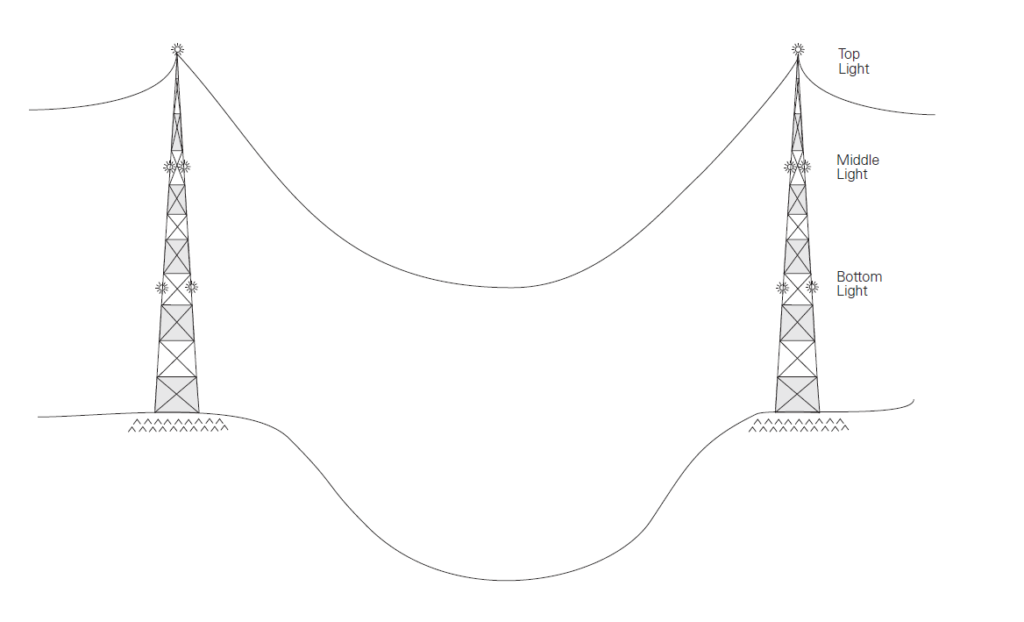
- where obstacle lights are used on a tower supporting overhead wires or cables (figure 4.19) they should be located at three levels:
a) on the top of the tower;
b) on the tower at the lowest level of the catenary of the wires or cables; and
c) at approximately mid-way between these two levels. - at each level the lights should be arranged to give full cover in azimuth.

Lighting of unserviceable parts of the movement area
4.106 Unserviceable parts of the movement area of an aerodrome used at night should be lit as follows:
- to delineate unsafe areas, lights should be spaced at intervals of not more than 7.5 m;
- to close off unserviceable sections of runways or taxiways, lights should be spaced at intervals of not more than 3 m.
Note: The normal runway and taxiway lighting within the unserviceable area should be suppressed.
4.107 A light used to mark unserviceable parts of the movement area should consist of a steady red light of sufficient intensity to ensure conspicuity, considering adjacent lights and the general level of illumination against which it would normally be viewed. It should have a minimum intensity of not less than 10 cd.
Lighting of vehicles
4.108 The responsibility for marking and lighting vehicles used on the movement area must be determined between the licence holder and the operators of the vehicles. Licence holders are responsible for ensuring that vehicles on the movement area are lit and/or marked as required, irrespective of ownership.
4.109 The specification for yellow flashing vehicle obstacle lights is given in chapter 6, appendix A, table 6A.1. Strobe lighting is unacceptable. Obstacle lights for
‘Follow-me’ vehicles only shall have characteristics described in figure 6A 19.
4.110 The lights specified should be fitted at the highest point of the prime mover vehicle.
4.111 The highest point of trailers should be fitted with steady red lights of not less than 10 cd.
4.112 Obstacle lights on vehicles should be switched on whenever the vehicles are within the movement area; however, the number of vehicles displaying flashing
lights should be restricted to the operational minimum.
4.113 Aerodrome ambulances, fire and rescue appliances should, in addition, carry blue flashing lights for use while carrying out emergency duties.
4.114 In conditions where emergency vehicles not normally based at an aerodrome are called upon for assistance, flashing blue lights, where fitted, should be operated within the movement area.
Light characteristics (see chapter 6, appendix A, table 6A.1)
Low intensity obstacle lights
4.115 On fixed obstacles, low intensity lights should be steady red and omnidirectional.
Medium intensity obstacle lights
4.116 Medium intensity obstacle lights should be steady red light.
High intensity obstacle lights
4.117 High intensity obstacle lights should be flashing white lights.
Replacement of lamps
4.118 Unserviceable lamps should be replaced as soon as possible and in any event within 24 hours. Periodic replacement of all lamps is advisable – the active life being deemed to be 80% of the rated lamp life. Where such preventive maintenance cannot be arranged, tungsten lamps may be underrun on voltage down to a minimum of 90% of rated voltage, provided that the specified output can be met. This procedure should increase lamp life to about 400% of the rated lamp life. When this procedure is used, preventive replacement should be carried out after the increased interval. The requirements for periodic change of lamps may, however, be varied or waived where fittings having acceptable performance and proved life are used.
Note: NOTAM action should be taken to promulgate unserviceabilities.
Periods of illumination of obstacle lighting
4.119 High intensity flashing white obstacle lights should be lit at all times throughout the day and night.
4.120 Steady red medium and low intensity obstacle lights should be lit:
- on and adjacent to an aerodrome from 30 minutes before sunset to 30 minutes after sunrise during the hours of availability notified in the UK AIP or by NOTAM;
- on en route obstacles from 30 minutes before sunset to 30 minutes after sunrise. Should switching present problems, these lights may remain lit continuously.
Table 6A.1 Characteristics of obstacle lights and low intensity aeronautical ground lights
| Lighting system (purpose of the light fitting) | Colour | Horizontal beam spread | Vertical beam spread | Minimum setting intensity (candelas) | Elevation projection angle (degrees) | Remarks |
|---|---|---|---|---|---|---|
| Low intensity approach | Red | Omnidirectional | +5 to +8 0 to +15 | 200 50 | – | |
| Low intensity runway edge | White | Omnidirectional | ±4 | 200 | 4.0 | Elevated fittings |
| Low intensity runway edge (battery) | White | Omnidirectional | ±4 to ±8 +8 to +8 | 50 10 | 4.0 | Portable elevated fittings |
| Low intensity threshold | Green | Omnidirectional | ±4 | 100 | 4.0 | Elevated fittings |
| Low intensity threshold (battery) | Green | Omnidirectional | ±4 | 40 | 4.0 | Portable elevated fittings |
| Low intensity runway end | Red | Omnidirectional | ±4 | 100 | 4.0 | Elevated fittings |
| Low intensity runway end (battery) | Red | Omnidirectional | ±4 | 18 | 4.0 | Portable elevated fittings |
| Taxiway edge | Blue | Omnidirectional | 0 to 6 6 to 75 | 2 0.2 | 3.5 | |
| Stopway | Red | Omnidirectional ± 6.5 | 0 to +15 | 100 | – | |
| Runway guard lights | Yellow | Omnidirectional ± 15 | 0 to +15 | 200 | – | 30 to 60 cycles per minute with periods of light suppression and illumination equal and opposite in each case |
| Low intensity obstacle (group A) | Red | Omnidirectional | 0 to +30 | 10 | – | Steady |
| Low intensity obstacle (group B) | Red | Omnidirectional | +5 to +8 0 to +15 | 200 50 | – | Steady |
| Vehicle obstacle | Yellow | 360º | ±10º (note 1) | 40 | – | Flash rate 60 to 90 minute. Maximum intensity not to exceed 400 Cd |
| Medium intensity obstacle | Red | Omnidirectional | ±4º | 2000 ±20% | – | Steady |
| High intensity obstacle | White | 120º | 3 | 200 000 day 20 000 dusk 2000 night | 0 | 40 flashed per minute (notes 2, 3, 4) |
Notes:
- The coverage requirement for ‘follow me’ vehicles only is illustrated in figure 6A.21.
- Where an intermediate high intensity obstacle light is fitted, the angle should be 3° for a light less than 92 m agl,
2° for a light between 92 m and 122 m agl, and 1o for a light between 122 m and 151 m agl. - If more than one light is fitted, the lights should flash simultaneously.
- Lights should flash sequentially if indicating overhead wires or cables.
Reference
UK Civil Aviation Authority 2019, CAP 168: Licensing of Aerodromes, Safety Regulation Group, London, viewed 24 October 2020, viewed 24 October 2020, < http://publicapps.caa.co.uk/docs/33/CAP%20168%20Issue11_Licensing%20of%20Aerodromes%2013032019.pdf>.

